


The AM-3 Radio is a 3rd Generation simple radio illustrating the progress made over 65 years of hobby transistors. The design uses tuning, detection, and amplification. There is no regeneration and/or reflexing of the signals received.
Starting with the coil, the inductor value is 355uH. A second coil with identical properties is then made. The two coils are 84 turns of #32 magnet wire wound on a 2" diameter plastic (hdpe or polypropylene) can with a length of 2". This allows three tuning configurations of parallel, series, and single coil.
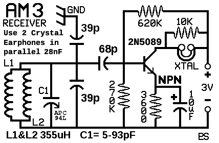
The tuning used is a straight-forward parallel resonance trap. For low cost and very good Q an APC-100 is employed. The fixed-value caps for the tuner MUST be of high Q and quality of construction. AVX or KEMET MLCC type ceramic 200V 5% are used. These have a Q value more than 1000 at 1000kHz. The Tuning fixed cap and Ground capacitor (39pF) have an input cap of 68pF. The coils are in parallel 1700kHz to 1100kHz, as a single coil 1200 to 800kHz, and in series below 850kHz.
The transistor is a 2n5089 NPN Silicon, a MPSA-18 can substitute. Gain of either choice is generally over 700. 'Good ones' can exceed 900. The detector/amplifier has been designed for power consumption of about 0.32mW (320uW) with the emitter current at 104uA. This low power allows the use of TWO crystal earphones in parallel. The ground used here is the telephone ground just like the old rocket-radios of the 50's and 60's. Connection is to the green wire. Use station wire if possible (solid wire cable as opposed to the stranded flat cable).
AT THE TELEPHONE OR THE TELEPHONE JACK
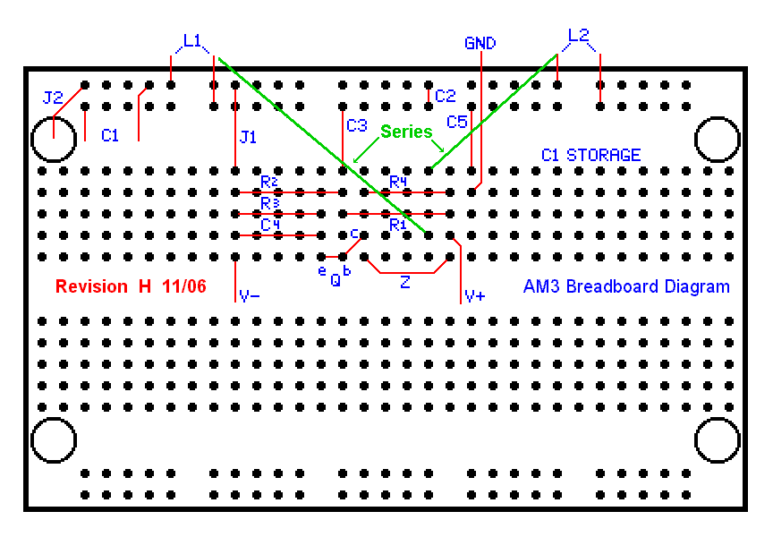
DURING THUNDERSTORMS.TIP: Cyrstal Earphones with soldered ends can get more signal to the ears by very carefully cutting the earphone solder connections off and stripping the 4 leads. The strands of wire inside are literally hair thin and delicate requiring skill and patience, even with the right tool. I tried this with a pair of sharp scissors, and I did get this to work. Its not easy, but the reward is a good solid COPPER contact for the phones. Since this is stranded wire, simply plugging in the connection is not possible. For a good method, find a European connector block, saw off two adjacent connections, and connect Left and Right earphone wires. The other side of the block connects to the circuit board by solid magnet wire. After making the new left and right connections, DISCONNECT THE GROUND, THEN THE BATTERY, and REMOVE THE TRANSISTOR. Place the board-side connections over the proper breadboard contact, and push the wire into the board. When both connections are installed and secure, REPLACE THE TRANSISTOR, then RECONNECT the BATTERY, and replace the ground last. The volume increase is quite notable!
The 312 logged receptions
Best viewed with Monaco TTF font. DOWNLOAD
You are visitor #
